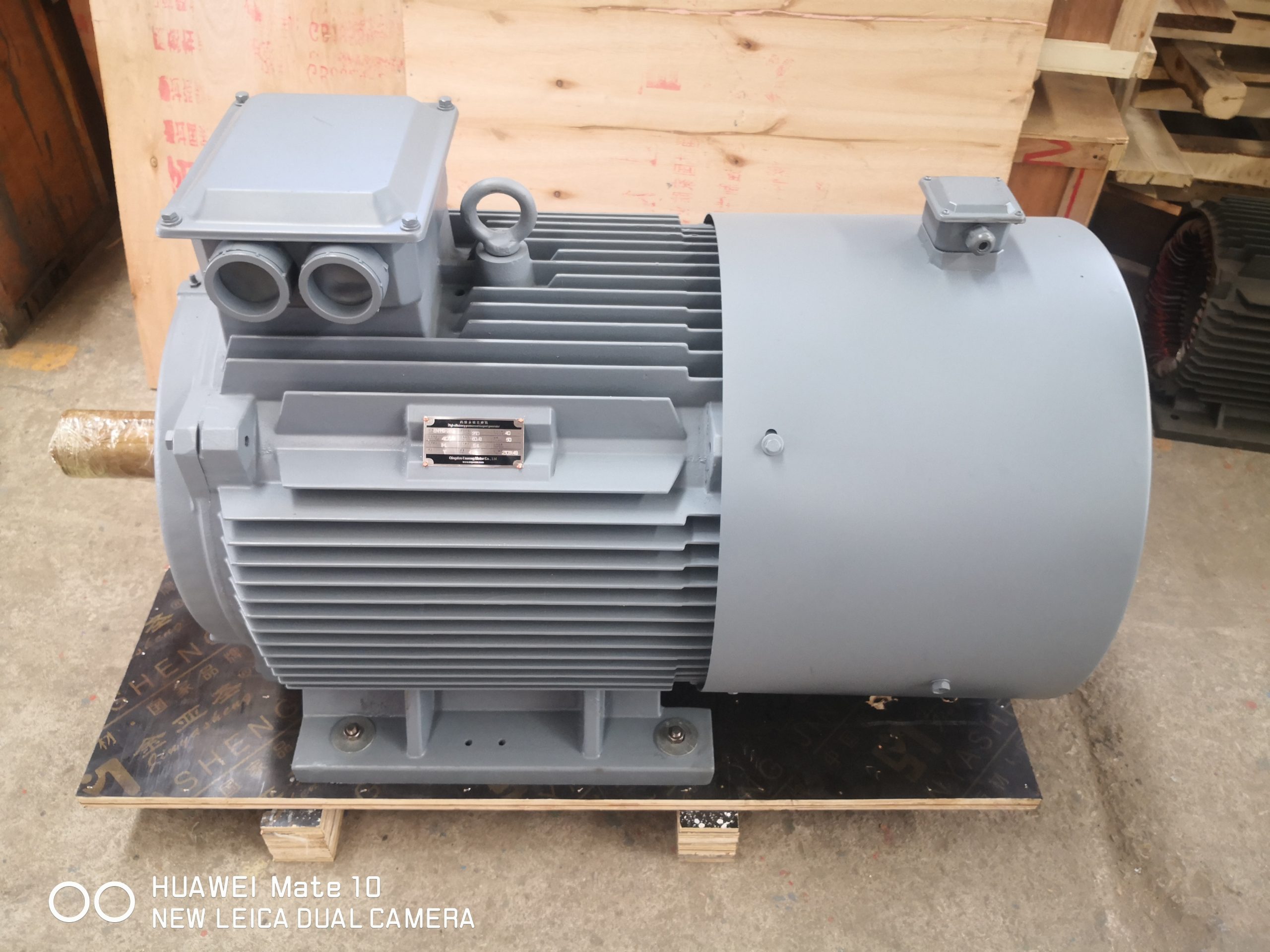
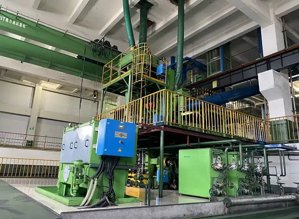
Define what direct drive removes
Direct drive describes a drivetrain architecture, not one universal motor construction. The motor connects to the load with fewer speed-reduction elements, and in some arrangements it can remove a gearbox, belts, sheaves, jackshaft or selected couplings. The exact boundary must be drawn for the existing and proposed systems. Only then can engineers compare losses, maintenance tasks, alignment points, spare parts and failure modes on the same basis.
ABB describes direct-drive permanent magnet motors that generate high torque at low speed without mechanical reduction, while Siemens describes high-pole permanent magnet torque motors for low-speed direct drives. These examples support the architecture concept, but they do not establish the suitability of a particular ENNENG model. Site torque, speed, structure and control requirements still govern the project.
Build the speed-torque envelope
The first calculation is a continuous and transient speed-torque envelope at the driven shaft. Include breakaway torque, normal process torque, upset conditions, acceleration time, minimum stable speed, overspeed scenarios and any reversing or inching operation. For conveyors, starting with material on the belt can differ sharply from empty running. For mills, process charge and starting sequence can dominate. For pumps and fans, the process curve and control method matter.
Do not convert a gearbox ratio into a motor speed and stop there. Check mechanical losses, service factors, inertia reflected through the old transmission and the torque that the new motor must supply during each event. If measured data are unavailable, identify the calculation method and uncertainty. A transparent envelope is more useful than one oversized torque number because it guides electromagnetic, thermal, drive and structural design together.
The structure becomes part of the motor system
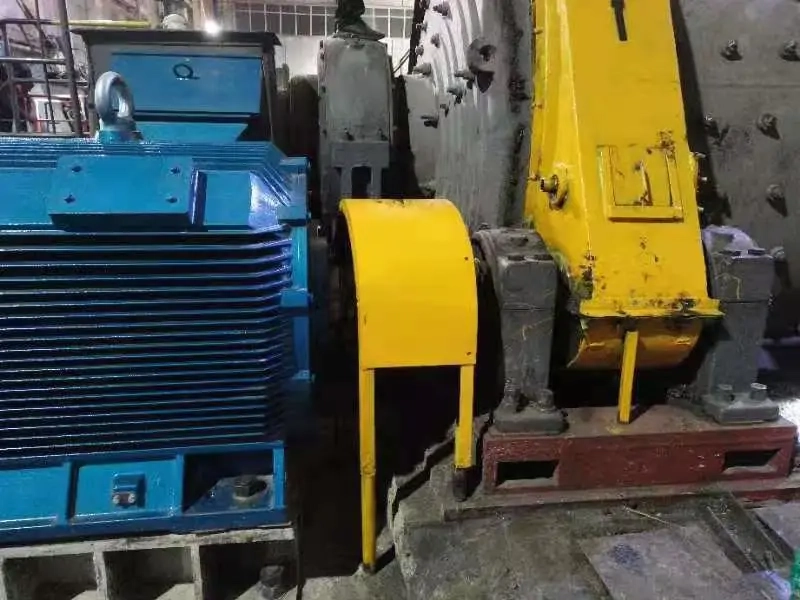
Removing a gearbox changes more than the component count. The gearbox may have provided mounting stiffness, shaft offset, bearing support or a convenient interface. A new direct-drive arrangement must define who carries radial and axial loads, how the motor is centered, how torque reaction enters the foundation and how alignment is maintained. Provide general arrangement drawings, shaft dimensions, bearing locations and allowable envelope.
Check foundation stiffness, resonances and torsional behavior across operating and transient conditions. Large-diameter, high-torque machines can introduce forces that were not applied to the old base in the same way. A mechanical review should also cover lifting, installation access, service clearances and how the machine can be uncoupled. These practical details often decide whether a retrofit can be installed without extended downtime.
Evaluate reliability without slogans
Fewer mechanical transmission elements can remove lubrication points, wear interfaces and alignment tasks. That can simplify maintenance, as official ABB and Siemens direct-drive materials explain for their own systems. The remaining components, however, become more critical. Motor bearings, cooling, sensors, drive electronics, cable routing and structural connections still require a maintenance and spares plan.
Create a before-and-after failure-mode review. List each component removed, retained or added, its inspection interval, likely failure signal and replacement method. Confirm whether site technicians can access the components and whether the plant has the required diagnostic tools. Reliability improvement is credible when it is tied to a specific architecture and maintenance plan, not when it is presented as an automatic result of the words direct drive.
Direct-drive RFQ checklist
Send the driven-equipment description, existing drivetrain drawing, motor and gearbox nameplates, shaft speed, continuous and peak torque, starting method, load profile, inertia, coupling details, bearing arrangement, voltage, proposed drive, environment, cooling limits and available installation envelope. Photographs with scale references are useful, but dimensioned drawings remain necessary.
For conveyors include belt speed, loaded start condition, incline and take-up arrangement. For mills include charge condition, starting sequence and any inching requirement. For pumps and compressors include the process curve, minimum speed and control objective. ENNENG can use this package to decide whether a TYDP or other low-speed configuration deserves detailed review.